3.7 Centreboard Design - By Trent Cornwall
|
I started with a blank piece of paper and tried to make no assumptions on any shapes, profile or cross section from what other people were using.
Obviously the first thing to do was measure the sizes that the centreboard had to fit into: 1) Class Rules - 9a: “Centreboard does not exceed 1370mm in length” 2) Centrecase opening 24mm x 300mm With a centrecase opening width of 24mm this means that for these foil thickness’ the chord length must be: Chord Thickness Chord Length 6% 400mm 8% 300mm 9% 267mm 10% 240mm 12% 200mm Obviously the 6% foil woud be too long a chord to fit down the case and the 12% may be marginal on area (unless possibly you built a non-tapered parallel profile board). Chord Thickness In light days the 3.7 centreboard has to generate lift at fairly low non-planing speeds and on windy days it must perform when we are planing upwind and be able to take quite abrupt changes in direction due to the short length of these boats. “A 9-10% thick section with a small leading edge radius followed by a fairing parabola over the forward 15% of the chord gives the best blend of both low and high speed behaviour.” - High Performance Sailing – Bethwaite Turbulent or Laminar?
There are two types of cross sectional profiles to choose from. The Turbulent flow profiles such as the NACA 0009 or 0010 which most people are familar with or more specific Laminar flow profiles. Laminar flow profiles are generally finer entry with the maximum width further back. Although Laminar profiles have the ability to generate much less drag, they can operate only at small angles of attack which Bethwaite found to be about 3 ½ degrees. On this basis I discarded using these and stuck with the traditional NACA profiles which operate more effectively over much wider angles of attack. 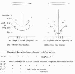
Fig 1. Drag Curves - Turbulent and Laminar – From High Performance Sailing – Bethwaite
Profile
It has been documented in many books that “Elliptical Lift Distribution” is the most desirable for centreboards and keels. This does not neccessarily mean an elliptical profile. 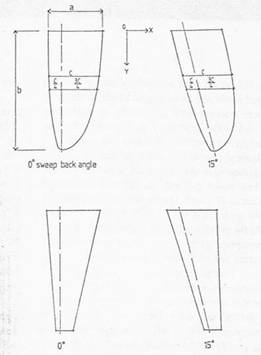
Fig 2. Elliptic Planforms -
“Elliptic Planforms are shapes that give rise to an elliptic lift distribution. To do this the planform does not have to be the shape of an ellipse (or semi-ellipse): a number of shapes could give an elliptic lift distribution if the section shape is varied appropriately. If one stays with a constant section shape, then an elliptic lift distribution results if the chord lengths are related to their position ‘y’ from the root by the equation of an ellipse”
- Symmetry of Sailing – Garrett
- A Trapezoidal shape as in the two lower figures in Figure 2 approximates an Ellipse in profile and generates Elliptical Lift Distribution.
Taper Ratio
The Board must be tapered in profile to approximate the ellipse and give the “elliptical lift distribution” mentioned above. The Taper Ratio of the trapezoid i.e. the width at the tip divided by the width at the base is theoretically optimum at 0.4 although this does vary marginally with aspect ratio. Figure 3 which is a graph of drag increase for different aspect ratios and tip widths shows that the tip width ratio has a reasonable range of variation before any noticable drag is induced. 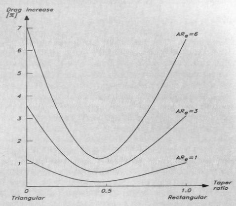
Fig. 3 – Principles of Yacht Design – Larsson
|
Aspect Ratio
Theoretically a foil with an infinite aspect ratio will generate the maximum possible lift for any profile. In the real world the majority of vortex drag is generated at the tip of the foil so it stands to reason that a higher aspect ratio foil will always be more efficient for a fixed area as there is effectively less tip area. Therefore the highest possible aspect ratio within the class rules must have the highest lift potential. With a class rule fixed maximum length of 1370mm there must be a trade off between maximum aspect ratio and minimum area to prevent leeway i.e. the highest aspect ratio/smallest centreboard you can get away with to still create enough lifting force and with the minimal drag component possible. Sweepback Angle
How much if any rake or sweepback angle should the centreboard have and what effect does this have? 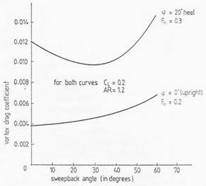
Fig. 4 -
“The effect of sweep angle on vortex drag when surface effects are taken into account. The lift produced by leeway is the same in both cases. For small boats which are sailed upright, zero sweepback is best. When heeled some sweep is beneficial. The optimum amount of sweep decreases with increasing aspect ratio and draft.”
- Symmetry of Sailing – Garrett
- Figure 4 clearly shows that a foil with a zero sweepback angle has the lowest vortex drag for a yacht sailing dead upright.
Conclusions
To achieve the highest possible aspect ratio with fixed overall length the chord length must be as short as possible. I opted for the 10% section on this basis and also as the easiest way to reduce drag is to reduce area. Also the shorter the chord the less area that may operate under turbulence once the flow had broken away. This makes my centreboard 240mm wide where it exits the centrecase. Remember that with the 3.7 when you talk about decreasing the foil % thickness to reduce drag you are actually increasing the chord length which is increasing the area and with this IS an increase in drag (as the maximum thickness is always the centrecase width aprox 24mm). This was also part of my reasoning for the maximum length and highest possible aspect ratio as all the lift is generated in the leading edge area. Regardless of which section was to be used I figured looking head on at the centreboard you would be displacing 24mm wide x aprox. 1100 deep, so best to cut down on the area by using a thicker % higher lift profile. I used a taper ratio of about 50% so as not to reduce the area too much. I actually chickened out while making it as I was originally intending to use 40% but the overall area looked way too small. There must be a minimum area required to generate the right amount of lift for each particular 3.7 rig/sailor setup and anything more must be just drag, anything less and too much leeway. I feel I must be fairly close for my rig, as in certain windstrengths upwind if I am pinching a bit much for the sail the boat feels like it crabs a little, then if a drop off a couple of degrees it seems to power up and generate a lot more lift. With a 50% taper ratio this makes the tip of my centreboard 125mm The Aspect Ratio of the centreboard is : (Length divided by average chord) 1310/((240 +125)/2)= 7.18 As there is about 1100mm below the boat I guess its effectively: 1100/((240 + 125)/2)=6.03 which is still very high. Compare with a full case length Short and Non-Tapered Centreboard (assume 100mm less than maximum length) 1000/300 = 3.33 AR Construction I constructed the centreboard using 3 pieces of Kahikatea laminated together for the core. After shaping I planed a trough on each side to lay the carbon unidirectionals in, faired over and then glassed with “S’ Glass. To get a thin trailing edge that would not deteriorate I then machined a groove down the trailing edge and glued in a 1mm thick piece of formica. Note Other people have used laminar flow foils which seem to work fine. They are like mentioned before much more critical for angle of attack (max 3 ½ degrees) and also the surface finish must be practically perfect to keep the flow attached so far back. If they are not then the flow can not stay laminar and breaks away at which point the foils cease to perform very well at all. References [1] Bethwaite, Frank; High Performance Sailing, 1993 Waterline Books. [2] Garret, Ross; The Symmetry of Sailing, 1996 Sheridan House. [3] Larsson, Lars & Rolf E Eliasson; Principles of Yacht Design, 1994 Adlard Coles Nautical. Back to tuning |
